 +86 13600513715

News
0102030405
Liftable Aeration System Installation: Expert Tactics to Prevent Cable Failures & Misalignment
2025-08-18
Liftable Aeration Pipe Installation: Critical Field Protocols from a Wastewater Systems Expert
After 18 years commissioning aeration systems across 3 continents, I’ve seen how improper liftable pipe installations cause cable snap failures, misaligned diffusers, and catastrophic basin damage – costing plants $200K+ in emergency repairs and 30% energy overconsumption. Unlike fixed diffusers, these dynamic systems demand precision in mechanical integration, corrosion control, and load distribution. Below are battle-tested protocols refined through decades of forensic failure investigations.
I. Pre-Installation: Beyond Basic Site Surveys
1.1 Structural Integrity Verification
Concrete Anchor Point Analysis:
-
Shear stress tolerance: Anchor bolts must withstand 5× operational load (min. 25 kN per lift point). In a Brazilian plant retrofit, undersized anchors tore from concrete during lift tests, collapsing 12 diffuser banks.
-
Corrosion protection: Stainless steel (316L) components require cathodic protection when chloride >500 ppm. Galvanic corrosion destroyed $140K of hardware in a coastal UAE plant within 8 months.
1.2 Material Compatibility Matrix
| Component | High-Chloride (>800 ppm) | Acidic Waste (pH<5) | Oily Wastewater | Critical Tolerance |
|---|---|---|---|---|
| Lift cables | 316L SS + PTFE coating | Aramid fiber | 316L SS | Max stretch: 0.2%/m |
| Guide rails | FRP with phenolic lining | Hastelloy C-276 | Ceramic-coated steel | Flatness: ±0.5mm/m |
| Diffuser membranes | Silicone | EPDM + acid inhibitors | PTFE | Pore uniformity: 95% |
| Ballast weights | Concrete with epoxy seal | HDPE encapsulated lead | Stainless steel | Density: 2.8±0.1 g/cm³ |
Failure Case: A petrochemical plant used standard EPDM membranes in pH 4.5 wastewater – membranes disintegrated within 3 weeks, releasing 8 tons of ballast into basins.
II. Mechanical Installation: The 4 Pillars of Reliability
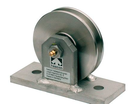
2.1 Cable & Sheave Alignment Protocol
-
Laser-guided alignment: Sheaves must be coaxial within ±0.1° deviation. Misalignment >0.5° causes cable fraying – a German plant replaced cables quarterly until laser calibration.
-
Pre-tensioning: Apply 15% operational load (e.g., 450 kg for 3,000 kg system) during installation to eliminate dead stretch.
-
Anti-fouling lubrication: Use marine-grade Teflon grease on sheaves – petroleum-based products dissolve in wastewater.
2.2 Diffuser Leveling Under Dynamic Load
-
Water-submerged calibration: Level diffusers when submerged under 1.5m water depth (simulates buoyancy forces).
-
Torque sequence: Tighten flange bolts in cross-pattern at 25 Nm increments to 85 Nm final torque.
-
Acceptance test: Lift/lower system 5 times at 0.3 m/s – diffuser tilt must remain <1°.
III. Hydraulic Integration: Avoiding Flow-Induced Failures
3.1 Air Header Connection Flexure
-
Expansion joints: Install stainless steel bellows with 15° angular movement capacity at every lift point.
-
Slip couplings: Allow 150mm vertical travel – rigid connections fracture during lifting.
-
Leak testing: Pressure test at 1.5× operating pressure (min. 10 bar) with system at max lift height.
3.2 Anti-Vortex Engineering
-
Basin floor clearance: Maintain 400mm gap between lowered diffusers and floor.
-
Flow deflectors: Install 45° vanes upstream if velocity >0.3 m/sec – unmitigated vortices displaced 40% of diffusers in a Taiwanese plant.
IV. Electrical & Control Safeguards
4.1 Load Monitoring Triangulation
-
Strain gauges: Mount on all lift cables with ±2% accuracy calibration.
-
Redundant sensors: Cross-verify with pressure transducers on hydraulic cylinders (if used).
-
Auto-shutdown threshold: Trigger alarm at 90% max load; cut power at 105%.
4.2 Corrosion-Resistant Wiring
-
Cable specifications:
-
Conductors: Tinned copper
-
Jacketing: Chlorosulfonated polyethylene (CSPE)
-
Minimum bend radius: 12× cable diameter
-
-
Conduit protection: Pressurized (0.2 bar) nitrogen-filled conduits prevent moisture ingress.
V. Commissioning: The 7-Step Performance Lockdown
-
Dry-cycle test: 10 lift/lower cycles without water
-
Buoyancy calibration: Submerge system, verify lift force <110% design
-
Air leakage test: 2-hour test at max operating pressure
-
Load asymmetry check: Measure cable tension variance <5%
-
Emergency stop verification: Cut power at 3 positions
-
Positional repeatability: 10 cycles to 5m depth – deviation <10mm
-
Basin sweep test: Laser-map diffuser positions at all heights
VI. Long-Term Maintenance: Data-Driven Protocols
Predictive Replacement Thresholds:
| Component | Replacement Trigger | Monitoring Tool |
|---|---|---|
| Lift cables | 3% elongation or 10% strand break | Digital caliper + ultrasonic tester |
| Sheave wheels | Groove wear >5% of cable diameter | Laser profilometer |
| Guide rollers | Vibration amplitude >4 mm/s² | Wireless accelerometer |
| Membrane seals | Compression set >35% | Durometer hardness test |
Critical: Recalibrate load cells every 6 months – signal drift caused uncontrolled descent in a Dutch plant, crushing 8 diffusers.