 +86 13600513715

News


0102030405
Design of UASB Technology
2025-06-06
Overview
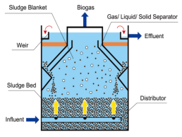
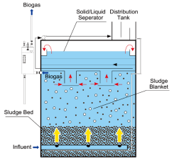
The Upflow Anaerobic Sludge Blanket (UASB) reactor is a widely used anaerobic wastewater treatment process designed to efficiently break down organic pollutants in the absence of oxygen. In this system, wastewater flows upward through a dense bed of granular sludge, where microorganisms metabolize organic matter, producing biogas (primarily methane and carbon dioxide) as a byproduct. A key feature of the UASB is its three-phase separator at the top, which effectively splits the generated biogas, treated water, and sludge, allowing for continuous operation without the need for mechanical mixing.
One of the main advantages of UASB technology is its high treatment efficiency, typically achieving 70–90% COD removal for high-strength organic wastewater. Unlike aerobic systems, it requires no aeration, significantly reducing energy consumption. Additionally, the process generates biogas, which can be harnessed as renewable energy. Another benefit is its low sludge production, minimizing disposal costs. UASB reactors are particularly suitable for industries such as food processing, breweries, and pulp/paper mills, where high organic loads are common. With proper operation, UASB systems offer a cost-effective and sustainable solution for industrial wastewater treatment.
Applicability
The Upflow Anaerobic Sludge Blanket (UASB) process is specifically designed for treating high-strength organic wastewater, typically requiring influent CODcr concentrations to exceed 1,000 mg/L for optimal performance. The system demonstrates limited tolerance for suspended solids (SS), with influent SS concentrations preferably maintained below 500 mg/L to ensure proper operation. When treating wastewater containing higher SS levels, pretreatment through coagulation-sedimentation or dissolved air flotation becomes necessary to prevent reactor clogging and maintain treatment efficiency. Additionally, for wastewaters with either excessively high suspended solids content or poor biodegradability, the installation of a hydrolysis tank for pre-acidification is strongly recommended to enhance overall treatment performance.
This technology is particularly suitable for industrial wastewater streams with high organic loads, where its unique combination of high treatment efficiency and biogas production offers both environmental and economic benefits. The UASB's ability to handle concentrated waste streams while generating renewable energy makes it an attractive solution for various industries, including food processing, breweries, and agro-industrial operations. However, careful consideration of influent characteristics and appropriate pretreatment measures are essential for ensuring stable, long-term operation of the UASB system.
Pretreatment Requirements
Pretreatment represents a critical component of UASB system design, directly influencing operational stability and treatment reliability. The comprehensive pretreatment scheme incorporates several essential units: screening devices, equalization tanks, and precise nutrient/pH/temperature control systems.
- Screening System
Fine screens, coarse screens, or hydro-sieves must be installed prior to the UASB treatment system. The final screening unit should have an opening size of 1-3mm, with Rotary Filters or other high-efficiency solid-liquid separation equipment recommended as replacements for conventional screens.
- Equalization Tank
(1) An equalization tank must be provided before wastewater enters the UASB reactor.
(2) The effective retention time in the equalization tank should be 6-12 hours.
(3) The tank must perform multiple functions including flow equalization, quantity regulation, pH adjustment, and prevention of insoluble matter sedimentation.
(4) Mechanical mixing is preferred for homogenization with a power density of 4-8W/m³. For small-scale treatment plants, aeration mixing may be used with an air-to-water ratio maintained between 7:1 to 10:1.
(5) Alkalinity supplementation and nutrient dosing devices must be installed in the equalization tank.
(6) A floating scum removal device should be installed at the effluent end.
(7) The tank bottom should be designed for easy sludge removal.
- pH Control
(1) The influent pH to the UASB reactor must be maintained between 6.5-7.8.
(2) Acid/alkali dosing should utilize metering pumps with automatic control, and the neutralization tank effluent should have a pH monitoring system linked to the dosing pumps.
- Temperature Regulation
(1) The mesophilic anaerobic process temperature should be maintained at 35±2℃. Heating equipment must be installed if this cannot be achieved naturally.
(2) Heat sources may include boiler steam or waste heat from biogas power generation. The piping system should be equipped with motorized valves and thermometers for automatic temperature control through feedback systems.
Design Calculations for UASB Reactors
- Calculation of UASB Reactor Effective Volume
The design parameters for UASB reactors are volumetric loading rate or hydraulic retention time (HRT). These parameters cannot be theoretically derived and are typically obtained through experimental studies, with different design loads for granular sludge and flocculent sludge reactors. Once the required volumetric loading rate (or HRT) is determined, the reactor's effective volume can be calculated using the following formulas:
(1) Volumetric Organic Loading Method
V = Q×S₀/Nᵥ
Where:
V = Effective reactor volume (m³)
Q = Wastewater flow rate (m³/d)
Nᵥ = Volumetric loading rate (kg CODcr/(m³·d))
S₀ = Influent organic concentration (kg CODcr/m³)
(2)Hydraulic Retention Time Method
V = K×Q×HRT
Where:
HRT = Hydraulic retention time (d)
K = Constant (safety factor)
- Reactor Tank Structure
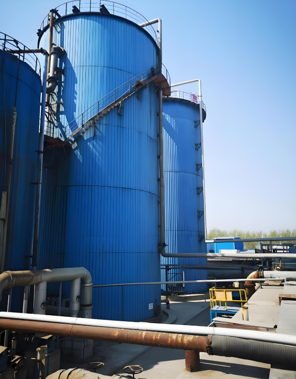
UASB reactor tanks typically employ circular or rectangular configurations, constructed using materials such as reinforced concrete, stainless steel, carbon steel with anti-corrosion coatings, enamel-assembled tanks, Lipp tanks, or fiberglass-reinforced plastic.
- Reactor Geometric Dimensions
(1) Reactor Height Design Principles
The reactor height design should consider both operational and economic factors. Operational considerations include:
① Increased upflow velocity enhances system turbulence, improving contact between sludge and organic matter;
② Excessively high upflow velocities may cause sludge washout, requiring velocity limitations that consequently restrict reactor height;
③ For conventional UASB systems, the average upflow velocity should generally not exceed 0.5 m/h;
④ The most economical water depth typically ranges between 4-6 m;
⑤ The height difference between the three-phase separator top and water surface should be no less than 0.6-1.0 m;
⑥ Multiple reactors (minimum 2) should be designed based on influent flow, with individual reactor volumes preferably not exceeding 2,000 m³.
(2) Reactor Area and Length-Width Ratio
For rectangular tanks, after determining volume and height, the length-width ratio should be established. For single tanks considering uniform water distribution and economy:
- Optimal length-width ratio should be below 2:1;
- A 4:1 ratio significantly increases costs;
- For shared-wall (or multi-unit) rectangular tanks, the length-width ratio substantially affects construction costs among other factors, requiring optimization;
- Practical experience suggests single tank width should not exceed 20 m;
- Tank length faces no restrictions when using channel or pipe distribution systems.
(3) Reactor Compartmentalization
Compartmentalized anaerobic reactors offer operational and maintenance advantages:
- Smaller unit sizes prevent distribution uniformity issues associated with large single tanks;
- Multiple tanks facilitate maintenance by allowing individual units to be taken offline without disrupting overall plant operation.
- Process Parameters
- For specific wastewater types, the reactor's process parameters should generally be determined through experimental studies. However, reference data from similar wastewater treatment projects may be used as a basis (see table below).
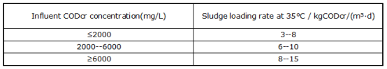
Under high-temperature conditions, the sludge loading rate of the reactor can be appropriately increased beyond the values listed in the table.
(2)The biogas production rate of UASB reactors typically ranges between 35–0.45 m³/kg CODcr. The biogas yield can be calculated using the following formula:
Qq = Q × (So - Se) × η
Where:
Qq = Biogas production (m³/d)
Q = Wastewater flow rate (m³/d)
η = Biogas yield coefficient (m³/kg CODcr)
So = Influent organic concentration (kg CODcr/m³)
Se = Effluent organic concentration (kg CODcr/m³)
(3)The sludge yield typically ranges between 05–0.10 kg MLSS/kg CODcr.
(4)The reactor temperature should generally be maintained at 35 ± 2°C (mesophilic)or 55 ± 2°C (thermophilic). Operation at ambient temperature is not recommended for optimal performance.
UASB Reactor System Design
1. Three-Phase Separator Design
Two typical configurations are available:
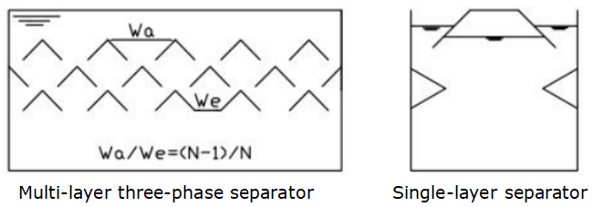
Key design specifications:
(1) The gap area of the gas collection chamber should occupy 15%-20% of the total reactor area.
(2) The height of the gas collection chamber should be 1.5m-2.0m.
(3) The inclination angle of separator plates should be 45°-60°.
(4) The gas-liquid interface in the collection chamber should maintain gas release while preventing scum layer formation. The liquid interface area below the separator should be calculated based on a gas release rate of 1-3 m³/(m²·h).
(5) The overlap between reflector plates and gaps should be 100mm-200mm to prevent gas entering the settling chamber.
(6) Gas pipes should have sufficient diameter for biogas extraction.
(7) Large collection chambers require foam-breaking nozzles in upper sections.
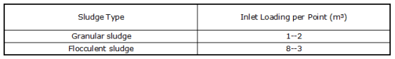
2. Water Distribution System Design
(1)UASB requires multi-point distribution, with recommended service areas per inlet varying by sludge characteristics (see table below).
(2)Distribution options include:
① Branch-pipe system:
- Outlets positioned 200mm above tank bottom at service area centers (typically 15-25mm diameter)
- 45° deflector plates required for bottom dispersion
② Multi-orifice single pipe system:
- Orifice velocity ≥2m/s
- Pipe diameter ≥50cm
- Pulsed intermittent feeding possible
③ Single-orifice distribution:
- Preferably uses specialized distributors
- Minimize elbows between distributor and outlets
- Vertical pipe velocity (top section) should be 0.2-0.3m/s
- Upper pipe diameter should exceed lower section
Note: All designs should ensure uniform hydraulic loading while preventing sludge bed disturbance. The selection depends on reactor scale, with branch systems preferred for >500m³ units and orifice systems for smaller installations.
3. Effluent Collection System Design
(1) The UASB reactor's effluent weir should employ triangular notches installed on the collection channel. The hydraulic loading should reference secondary settling tank standards, with weir head ≥25mm and water level at the midpoint of the triangular notch.
(2) Effluent collection devices must be installed at the reactor top to ensure uniform withdrawal of treated wastewater.
(3) Rectangular reactors should utilize multiple parallel weirs with multi-channel collection.
(4) Circular reactors preferably adopt radial multi-channel or polygonal channel collection.
4. Sludge Discharge System Design
(1) UASB reactors typically employ gravity-driven sludge discharge.
(2) Sludge withdrawal points should be located at:
- The reactor base (primary point)
- Upper-middle sludge zone (secondary point 0.5-1.5m below clarifier interface)
(3) Longitudinal multi-point discharge is required for rectangular tanks.
(4) Multi-orifice feed pipes may dual-function as sludge discharge and drainage pipes.
5. Heating and Insulation System
(1)The UASB reactor temperature should be maintained at 35±2°C (mesophilic)or 55±2°C (thermophilic). If the influent wastewater temperature is insufficient, a heating system must be installed prior to the UASB system.
(2)Heating methods for UASB reactors include:
- Heat exchanger systems
- Direct steam injection
- Heating can be applied to:
- Direct influent heating
- Recirculation heating loops
- Internal reactor heating
(3)For heat exchanger systems:
- Selection depends on wastewater characteristics, medium temperature, and target temperature
- Required heat transfer area should be calculated via thermal balance with 10-20% design margin
(4)Heat Load Calculations
Heating requirement to 35°C (Qₕ)
Qₕ = Q × λf × Cf × (35 - T) / 3.6
Where:
Qₕ = Heat demand (W)
Q = Flow rate (m³/h)
λf = Density (t/m³, 1 for water)
T = Influent temp (°C)
Cf = Specific heat (kJ/(kg·°C), 4.187 for water
Heat loss maintenance (Q₀)
Q₀ = A × K × (35 - T₀) / 3.6
Where:
A = Reactor surface area (m²)
K = Overall heat transfer coefficient (kJ/(m²·h·°C))
T₀ = Ambient temp (°C)
- value calculation:
K = 1/(α₁ + d₁/λ₁ + d₂/λ₂ + α₀)
Where:
α₁, α₀ = Heat transfer coefficients for inner (liquid-wall) and outer (wall-air) surfaces respectively
d₁, d₂ = Thicknesses of the first and second insulation layers (m)
λ₁, λ₂ = Thermal conductivities of the first and second insulation layers (kJ/(m·h·°C))
α₁ (liquid-wall interface) = 8,380-16,760 kJ/(m·h·°C)
α₀ (wall-air interface) = 84 kJ/(m·h·°C)
Total heat demand: Qₜ = Qₕ + Q₀
- When excessive heat loss occurs due to structural factors:
- Apply polyurethane foam, polystyrene boards, or fiberglass panels
- Insulation thickness should be optimized based on K-value requirements
Note: Steam sources may utilize boiler steam or waste heat from biogas cogeneration, with automated temperature control via motorized valves and PID controllers.