+86 13600513715

News


0102030405
Design and Case Studies of Water Treatment Engineering for RAS
2025-06-16
Process Flow
The construction of an industrialized recirculating aquaculture system (RAS) primarily includes aquaculture facilities, culture tanks, Water Treatment Systems, and associated technologies. The design and implementation should be based on comprehensive analysis of local climatic conditions, environmental factors, and biological characteristics of the target species, adhering to the principles of practicality, energy efficiency, and high performance. Advanced technologies and equipment should be employed to create an optimal aquaculture ecosystem while aligning with China's national conditions.
RAS construction is a specialized small-scale engineering project involving multiple disciplines such as marine science, biology, electromechanical engineering, instrumentation, hydraulics, construction, and aquaculture technology. Its development must rely on scientific research, integrating multidisciplinary expertise to ensure the system is technologically advanced, economically viable, and operationally manageable, ultimately achieving high-efficiency and eco-friendly production.
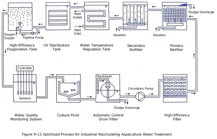
After repeated testing and optimization, the finalized process flow is as follows:
Culture Tank → Drum Filter → High-Efficiency Filter → Biofilter →Temperature Regulation Tank → UV Sterilization Unit → Oxygenation Chamber → Water Quality Monitoring System → Culture Tank(Figure 9-13).
Engineering Design Case of Water Treatment System
The following is a specific case study. Based on the previously studied process flow, the system is designed with:
- Fish culture area: 1,000 m²
- Waterdepth: 0.8 m (effective water volume: 800 m³)
- Maximumwater circulation rate: 400 m³/h (adjustable flow rate)
- Waterreuse rate: >95%
1. Elevation Design
- Watertreatment room: Floor area of 368 m², with a ground elevation of ±0.00 m.
- Low-level sump & pump room: Located at a -1.8 m elevation.
- Biofilter: Constructed with reinforced concrete, designed at a higher elevation:
- Bottom elevation: +1.5 m
- Top elevation: +3.5 m
- Effective water volume: 100 m³ (10:1 ratio to fish tank volume).
Energy-Saving Circulation Design:
- Single-stage lifting: Water is pumped from the sump to the biofilter via a high-efficiency filter.
- Gravity flow: Water then flows sequentially through:
- Temperature regulation tank → UV sterilization unit → Oxygenation chamber → Culture tanks.
- Flow control: Adjustable via pump operation and valve regulation.
Advantages: Energy-efficient, easy operation, and low maintenance.
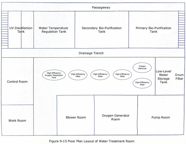
2. Water Treatment Room Layout
- Structure: Single-story with a low-arched translucent roof, PVC panel ceiling, and 4 skylights.
- Thermal benefits: Wind-resistant, summer heat insulation, and winter warmth retention (Figure 9-15).
- Dimensions: 24.5 m (length) × 15.0 m (width), east-facing.
Equipment Arrangement (Three Rows):
①East side (Power equipment):
-
- Pumproom, oxygen generator room, Roots blower room.
②Middle row (Filtration & oxygenation):
-
- Drumfilter, high-efficiency filter, protein skimmer, oxygenation chamber.
③West side (Treatment units):
-
- Primary/secondary biofilters, temperature regulation tank, modular UV sterilizer.
- Control room & workspace: South side.
Benefits: Organized installation, operational convenience, and streamlined maintenance.
3. Hydraulic Flow Design
- Fish tanks:
- Circular shape with two inclined inlet pipes.
- Conical bottom with central drainage.
- Rotational flow creates radial currents for self-cleaning.
- Sump drainage:
- Open-channel uniform flow for natural aeration.
- Biofilters:
- Primary: Top inlet, bottom outlet.
- Secondary: Bottom inlet, top outlet.
- Flow pattern: Up-down composite movement ensures uniform contact with biofilm.
- UV sterilizer:
- Channel-type design with alternating high/low inlets to prolong exposure time.
- Oxygenation chamber:
- Oxygen-saturated water is delivered via closed PVC pipes to prevent O₂ loss.
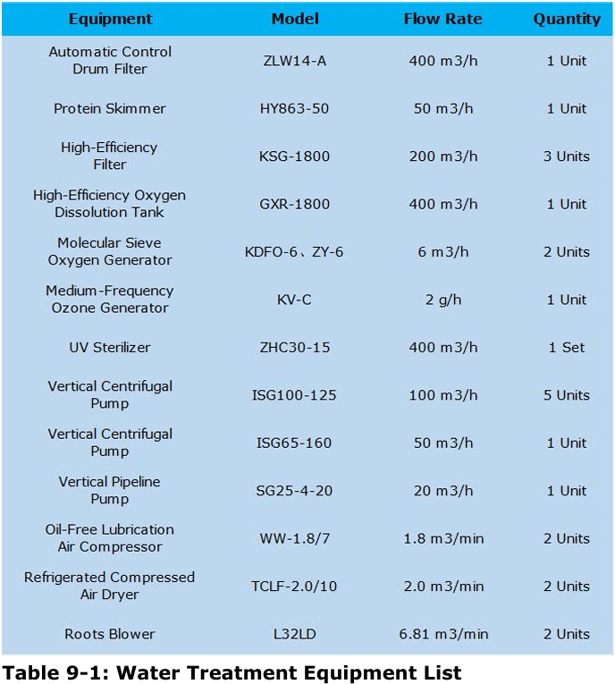
4. Water Treatment Equipment Specifications
See Table 9-1 for details on models, flow rates, and quantities.